Full code checking member optimization can be applied to standard steel shapes based on the following codes:
The calculations performed encompass all the code requirements (including the local buckling criteria for slender compression elements in Appendix B of the 2nd, 3rd, and 9th Edition AISC codes) except those noted in the Limitations section of this document
How To Apply a Steel Design Code
Note:
The Hot Rolled Steel Design
Parameters Spreadsheet records
the design parameters for the steel code checks and may be accessed by
selecting Beams
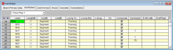
The pull down list at the top of the spreadsheet allows you to toggle between floors.
You may assign a unique Label to all of the members. Each label
must be unique, so if you try to enter the same label more than once you
will get an error message.
The
In RISAFloor, the beam design is performed for each member based on the design parameters defined for that beam. If these values are not entered, they will be automatically calculated based on deck and framing.
When RISAFloor creates a 3D model, all the Lateral Beams that came originally from Floor will have a "link list" that defines those beam parameters for every section along its length. In this way, the unbraced lengths used in RISAFloor should be identical to the ones used in RISA-3D.
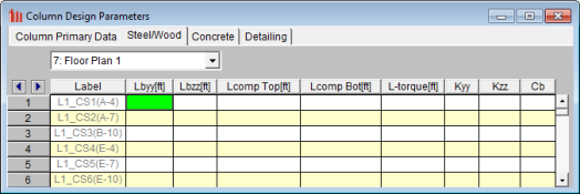
In RISAFloor, the column design is performed for each floor based on the design parameters defined for that floor level. That way, each level may have a different K value, unbraced length, Cb value and such.
When RISAFloor creates the 3D model for lateral analysis, the column information transferred into the RISA-3D model will not necessarily be the same as the values used in the RISAFloor analysis. Instead, the most conservative value for unbraced length will be used for the entire length of that column lift unless a user defined value is entered in RISA-3D.
See the Unbraced Lengths topic.
See the Unbraced Lengths topic.
See the Unbraced Lengths topic.
This box is used to indicate whether the beam is to be designed as composite with a Composite Deck (if present). For more information see Composite Beam Design.
Note:
B-eff Left and B-eff Right are the effective widths of the slab for composite beam design. If this value is left blank the effective widths will be calculated automatically as the smaller of half the distance to the adjacent beam and one eighth of the beam span. The calculated widths are listed on the Member Detail report. See Hot Rolled Steel Design – Composite for more information on how these are automatically calculated by the program.
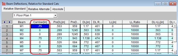
Use this field to manually enter an explicit camber value. If this entry is left blank, the program will design camber based on your Member Design Rules.
After solution, the camber is reported in the Member Detail Report and Deflection Results spreadsheet. The member detail report displays the camber under the deflections category. The deflection and span ratio results in the code checks section are calculated after the beam has been cambered. The deflection diagram in the report does NOT include the camber.
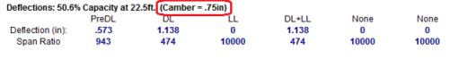
The Deflection Results spreadsheet displays a column with the camber specified for each member. Again, the deflection and span ratio results in the code checks section are calculated after the beam has been cambered.
Note
RISAFloor is capable of designing wide flange steel beam members for openings in the web. Both rectangular and circular web openings are supported and may be placed in wide flanges of both non-composite and composite beams. Additionally, reinforcements may be considered along the top and bottom edge to reinforce the web openings.
The design of the web openings follow the guidelines set forth by the AISC Design Guide #2 - Steel and Composite Beams with Web Openings.
The following Design Codes are supported for Web Openings:
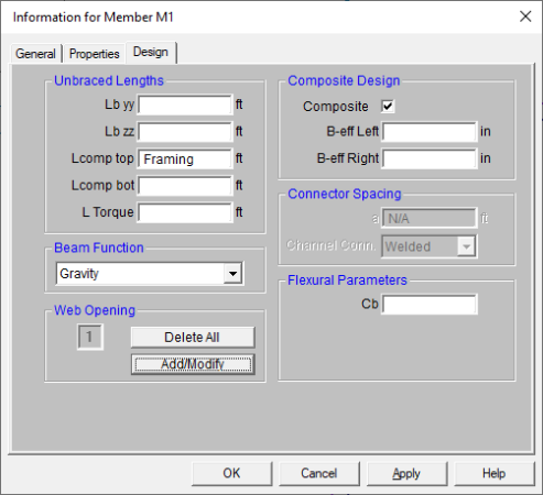
Web openings may be added to an individual beam by double clicking on the beam and navigating to the Design tab and clicking on the Add/Modify button as shown below:
Web openings may also be added several beams at once by going to the Modify --> Beams --> Beams from the Modify Menu (or click on the Draw or Modify Beam button  in the Graphic Editing Toolbar) and then navigating to the Web Opening tab as shown below:
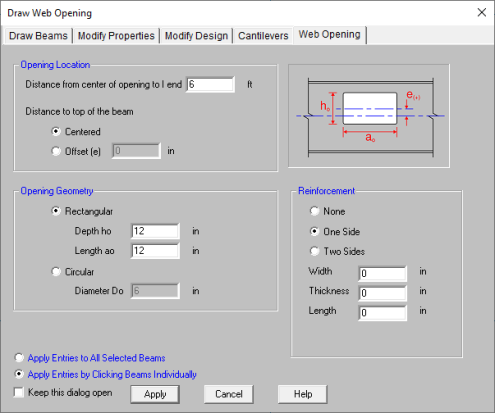
Opening Location - This allows you to specify the location of the web opening along the length of the beam and if it is to be centered on the beam or offset from the center line of the beam.
Opening Geometry - This allows you to choose the shape of the web opening as well as the dimensions of the opening.
Reinforcement - This allows you to specify the reinforcement of the web opening.
Alternatively, web openings can be added, modified, or deleted through the Beams spreadsheet as shown below:
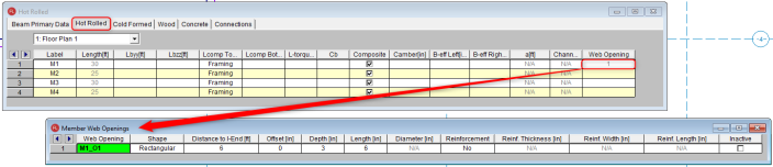
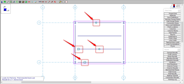
When a web opening has been defined onto a beam, the plan view will graphically show the location of the web opening as well as the shape (rectangular or circular) as shown below:
Limitations:
Cm Coefficients are described in Chapter H of the 9th Edition AISC (ASD) code. If
these entries are left blank, they will be automatically calculated.
The Cm value is influenced by the sway condition of the member and is dependent on the member's end moments, which will change from one load combination to the next, so it may be a good idea to leave these entries blank.
Note
Cb Factors are described in Chapter F of the AISC code and are used in
the calculation of the nominal flexural strength, Mn. If
this entry is left blank, it will be calculated automatically for AISC
code checks.
The calculation of Cb is based on the unbraced length of the compression flange and the moment diagram for the unbraced segment in question. If a specific unbraced length is entered by the user, the program cannot interpret the location of brace points and the Cb value will default to '1.0'. In some cases, it may be better to enter 'segment' as the unbraced length for a physical member. When 'segment' is entered, the Cb value will be calculated individually for each segment of the beam based on that segment's moment diagram.
Notes:
The type of connection for double channels is reported in the Channel Conn. column. This input is only for back to back channels and is used in the calculation of KL/r.
For double channels, the connector spacing ‘a’ is used in the calculation of KL/r. This input is only used for back to back channels.
Increasing of allowable stresses may be allowed when forces are transient. You may enter an ASIF factor on the Load Combinations Spreadsheet to allow the increase for a specific load combination. The ASIF factor is then applied to the allowable stresses in accordance with section A5. The ASIF factor also is applied to the Euler values (F'e).
Note
Setting the ASIF factor to a value greater than '1.0' will not cause the capacities to be increased by that factor. However, setting the ASIF factor to a value greater than '1.0' is used as a flag to use of the seismic compactness criteria of Table D1.1 of AISC 341-22 Seismic Provisions of Steel Buildings. Specifically we will use the limiting width-thickness ratios from this table for capacity calculations (for compression flange local buckling for example). In these cases, we use Table D1.1 of AISC 341-22 as opposed to Table B4.1 of AISC 360-22.
Wide Flanges:
Rectangular Tubes - Lateral torsional buckling is checked per section F7.4, however this section only applies to strong axis bending.
Code Checks - For combined bending and tension (Section H1.2) the code-allowed modification of Cb is not applied. For combined bending and compression, Section H1.3 is not considered, meaning that the program can be over conservative in some situations.
Single Angles - Single angles in compression are not checked for Section E4 because no standard single angle shapes have a slenderness (b/t) > 20. They are also not checked for Section E5 as there is insufficient information regarding the connections and usage of the member.
WT and LL Shapes - This code does not address the rare case where Lateral Torsional (or Flexural Torsional) Buckling occurs for WT's and double angles bent about their weak axis. Therefore, only yielding is checked for weak axis bending.
Double Channels -Double channel connector spacing requirements are not checked. Additionally, double channel design is only available in AISC 360-10 and later codes.
Wide Flanges:
Code Checks - For combined bending and tension (Section H1.2) the code-allowed modification of Cb is not applied. For combined bending and compression, Section H1.3 is not considered, meaning that the program can be over conservative in some situations.
Single Angles - Single angles in compression are not checked for Section E4 because no standard single angle shapes have a slenderness (b/t) > 20. They are also not checked for Section E5 as there is insufficient information regarding the connections and usage of the member.
WT and LL Shapes:
Wide Flange Shapes - Code checks for shapes that qualify as plate girders, as defined by Chapter G, are not performed. Plate girders that can be checked by the provisions of Chapter F will have code checks calculated.
Channels - The AISC 9th Edition (ASD) specification does not specifically address the allowable stress for weak axis bending of channels. Therefore, the program uses the most similar formula for the weak axis bending of wide flanges (0.75*Fy). For a complete and thorough treatment of channel code checks, refer to the LRFD specification.
RE Shapes - Rectangular bar members (on-line shapes) are assigned allowable bending stresses for the yielding limit state only. Lateral torsional buckling is not considered because the ASD code doesn't directly address this for rectangular shapes. The strong axis bending stress is assigned as 0.66*Fy and the weak axis bending stress is assigned as 0.75*Fy. If you have a case where lateral torsional buckling may govern, you should use the LRFD code, since the LRFD code does address this limit state.
Wide Flange Shapes - LRFD code checks for shapes that qualify as plate girders as defined by Chapter G are not performed.
Single Angles - Single angles are only checked for Euler buckling. They are not checked for Flexural-Torsional buckling.
Prismatic Wide Flanges with Unequal Flanges - ASD code checks for prismatic WF members with unequal flanges are also limited to shapes that have the compression flange area equal to or larger than the tension flange area. LRFD code checks currently cannot be performed for prismatic WF members with unequal flanges.
Single Angles - Code checking (LRFD or ASD) on single angle shapes is based on P/A (axial load/axial strength or axial stress/allowable axial stress) only. This is because the load eccentricity information needed for a meaningful bending calculation is not available. Only Euler buckling is considered for single angles, flexural-torsional buckling is NOT considered. Single angles will have the following message displayed on the Code Check Spreadsheet to remind the user of the axial only code check: "Code check based on z-z Axial ONLY"
In some instances, code checks are not performed for a particular member. A message explaining why a code check is not possible will be listed instead of the code check value. You may click the cell that contains the message and look to the status bar to view the full message. The following are the messages that may be listed:
This message is displayed when the member is not defined with a database shape, a steel code is not specified on the Model Settings or no units were specified. For LRFD this message is displayed if the steel yield stress is less than 10ksi.
The ratio h/tw exceeds the limiting criteria listed in Table B5.1. This means Chapter G (plate girders) governs.
The axial compressive stress for the member is greater than the Euler buckling stress (per ASD criteria), meaning the member is unstable. A code check can not be calculated.
A tube is failing to meet the depth/width requirements laid out in Section F3-1 of the ASD code. The depth of the tube is the full nominal depth, which the width is taken as the full width minus 3 times the thickness. Section B5-1 specifies this calculation for the width when the fillet radius is not known.
This message appears for ASD code checking when Appendix B calculations are being done for a Tee or Channel shape and the shape fails to meet the requirements of Table A-B5.1, Limiting Proportions for Channels and Tees.
This message appears when Appendix B calculations are being done for a pipe shape and the diameter/thickness ratio exceeds the limit of 13000/Fy specified in Section B5-b for ASD, Section B5-3b for LRFD.
Section B7 recommends that KL/r for compression members
not exceed 200. For the ASD 9th edition code, a procedure is presented to handle
when KL/r exceeds 200. Thus, for ASD 9th edition, KL/r>200 is permitted. For all other AISC codes no guidance is provided as to what to do if KL/r>200, so exceeding this limit is not permitted.
The requirements for Wide Flange members with unequal flanges in the LRFD, Appendix F1, are not addressed.
Parameters controlling the steel design are entered on the Member Design Parameters spreadsheet. These parameters are entered on a per member basis, and control the code checking on a per member basis.
w1 is the coefficient to determine equivalent uniform bending effect in beam-column, as described in Section 13.8.5 of CSA S16-09. If left blank, RISAFloor will calculate it. The w1 value is dependent on the member's end moments, which may change from one Load Combination to the next. Therefore it is a good idea to leave this entry blank and let RISAFloor calculate it.
w2 is the coefficient to account for increased moment resistance of a laterally unsupported doubly symmetric beam segment when subject to a moment gradient, as described in Section 13.6a of CSA S16-09. If left blank, RISAFloor will calculate it. The w2 value is dependent on the moment in the member, which may change from one Load Combination to the next. Therefore it is a good idea to leave this entry blank and let RISAFloor calculate it.
It is assumed the transverse load on the member is occurring through the member's shear center. This means secondary torsional moments that may occur if the load is not applied through the shear center are not considered.
Tapered Wide Flanges - No code checking is done for "Tapered WF" members which have different "Start" and "End" Depths, or which have top and bottom flanges of different widths. In other words, the "Tapered WF" may only be used for prismatic, doubly symmetric sections.
Single Angles - Single angles in compression are not checked for Clause 13.3.3.2 or 13.3.3.3 because there is insufficient information regarding the connections and usage of the member. They are not checked for Clause 13.3.2 (Flexural-Torsional Buckling) either. Instead they are checked for Euler Buckling about their geometric or principal axes per Clause 13.3.1. The slenderness classification for single angles is based on the longer leg.
S16-09 recommends using a "rational analysis" to account for lateral-torsional buckling and shear checks on single angles, so RISA uses the AISC 360-10 (14th Edition) provisions for these checks.
Class 4 Members - Members with both Class 4 (slender) webs and Class 4 (slender) flanges are not designed. Per S16-09, Clause 13.5.c.i these members must be designed per S136-07. Where only the web or the flange is Class 4 (slender) the capacity is determined per the provisions of S16-09, Clause 13.5c.
The code is not clear on whether this applies to WT, Double Angle, and Single Angle members, since they do not have a "web". Therefore, for these member types, the program calculates an effective (reduced) yield stress for each leg/flange/stem and uses the smallest value for the entire section.
Pipes and Round HSS - The code does not address how to determine the shear capacity of Class 3 or Class 4 (Noncompact, Slender) pipes. Therefore no design is done for those members. Class 1 and 2 member capacities are determined per the provisions of S16-09.
Shear Capacity - The code does not address how to determine the shear capacity of WTs, Double Angles, or Single Angles where shear buckling is a consideration (S16-09 Clause 13.4.3). Therefore no design is done for members where d/w or bel/t exceeds 1014/(Fy)1/2.
Welded Reduced Flange (WRF) Members- Since these members are classified within RISA as "Tapered", there is currently no design done for them. This limitation will be removed in a future release.
Torsional Buckling and Flexural Torsional Buckling (S16-09 and earlier) - The limit states of torsional buckling and flexural torsional buckling are not considered for wide flange and channel members. This means that the value Fez is not calculated for these members per Clause 13.3.2. The program takes the lesser of Fex and Fexy for axial buckling capacity for the S16-09 and earlier codes. These limit states are fully considered for S16-14 because an Ltorque input was added for S16-14 that was not present in earlier code implementations.
Compressive Strength (S16-09 and earlier) - For the equations in section 13.3.1, the parameter "n” is assigned a value of 1.34 for all shapes for S16-09 and earlier codes. This is conservative for WWF shapes and HSS shapes that are stress-relieved. For S16-14, members designated as type "Tapered WF" use n = 2.24 while members designated as type "WF" use n = 1.34.
Double Channels - Double channel design for Canadian code is only available in S16-14. Connector spacing requirements are not checked for double channels.
The Canadian code does not address the rare case where Lateral Torsional (or Flexural Torsional) Buckling occurs for WT's and double angles bent about their weak axis.
Tapered Wide Flanges - The AISC LRFD 2nd code is used to perform code checks on Tapered WF shapes when the Canadian code is specified. The Canadian code CAN/CSA S16.1-94 does not address web-tapered members.
Single Angles - Code checking on single angle shapes is performed for tension only. Single angles will have the following message displayed on the Steel Code Check Spreadsheet to remind the user of the tension only code check: "Single Angle code check based on Axial Tension ONLY"
Please see Single Angle Stresses for more information on the calculation of single angle stresses.
Slender Shapes - Shapes with any slender elements are not supported for axial compression. Shapes with slender webs or flanges are not supported for flexure. These shapes use the criteria in the CAN/CSA S136 code, which is not supported at this time.
When a code check is not performed for a particular member a message explaining why a code check is not possible will be listed instead of the code check value. You may click the cell that contains the message and look to the status bar to view the full message. Following are the messages that may be listed specifically for the Canadian Code:
The maximum L/r ratio for this tension member exceeds the limit shown in Section 10.2.2 of the CAN/CSA S16.1-94 code.
The maximum L/r ratio for this compression member exceeds the limit
shown in Section 10.2.1 of the CAN/CSA S16.1-94 code.
Compression strengths are not calculated for shapes that contain elements where the width to thickness ratios are classified as “slender”.
Flexural strengths are not calculated for shapes which have a web depth to thickness ratio classified as “slender”.
Flexural strengths are not calculated for shapes which have a flange width to thickness ratio classified as “slender”.
Compression strengths are not calculated for single angle members.
Parameters controlling the steel design are entered on the Member Design Parameters spreadsheet. These parameters are entered on a per member basis, and control the code checking on a per member basis.
Section 4.8.3.3.4 of the British code describes the m coefficient. If these entries are left blank, RISA will calculate them. The m value is influenced by the sway condition of the member and is dependent on the member's end moments, which will change from one Load Comb to the next. It's a good idea to leave these entries blank and let RISA calculate them.
This coefficient is discussed in Section 4.3.6.6 of the BS5950-1:2000 code and is used in the calculation of the flexural strength. If this entry is left blank it will be calculated automatically. This value also is impacted by the member's sway condition and is dependent on the member's end moments so it may be a good idea to let it be calculated internally. An exception to this would be for cantilever members in sway frames, this value should be 1.75, and it will be automatically calculated as 1.0. This will be addressed in a future program version.
It is assumed the transverse load on the member is occurring through the member's shear center. This means secondary torsional moments that may occur if the load is not applied through the shear center are not considered.
Single Angles - Single angles are checked for axial and shear forces only. No bending is considered at this time. A later release will consider the requirements in Annex I4 for single angles.
Secondary Moments per Annex I - The program does not yet consider the internal secondary moments described in Annex I.
Parameters controlling the steel design are entered on the Member Design Parameters spreadsheet. These parameters are entered on a per member basis, and control the code checking on a per member basis.
If these entries are left blank, RISA will calculate them per Annex B of the 2005/ 2014 EuroCode otherwise the user can choose to override the calculation by manually entering a value. The Cm value is influenced by the sway condition of the member and is dependent on the member's end moments, which will change from one Load Combination to the next. It's a good idea to leave these entries blank and let RISA calculate them.
For HSS Tubes, the program always uses Table B.1. For other members not subject to torsion deformations (wide flange members with an unbraced length equal to zero) the program will use Table B.1. for the 2014 code. All other members, the program will use table B.2.
If this entry is left blank, RISA will calculate it per Table B.3 in Annex B of the 2005 EuroCode, otherwise the user can choose to override the calculation by manually entering a value. The CmLT value is influenced by the sway condition of the member and is dependent on the member's end moments, which will change from one Load Combination to the next. It's a good idea to leave these entries blank and let RISA calculate them.
Section 5.5.4 (7) of the EuroCode describes the Bm coefficients. If these entries are left blank, RISA will calculate them. The Bm value is influenced by the sway condition of the member and is dependent on the member's end moments, which will change from one Load Comb to the next. It's a good idea to leave these entries blank and let RISA calculate them.
This coefficient is discussed in Section 5.5.4 (7) of the 1992 EuroCode code and is used in the calculation of the flexural strength. If this entry is left blank it will be calculated automatically. This value also is impacted by the member's sway condition and is dependent on the member's end moments so it may be a good idea to let it be calculated internally. An exception to this would be for cantilever members in sway frames, this value should be 1.75, and it will be automatically calculated as 1.0. This will be addressed in a future program version.
If this entry is left blank, RISA will calculate it per the explicit equation presented in the widely accepted article "Lateral-Torsional Buckling of Steel Beams: A General Expression for the Moment Gradient Factor" by López, Yong, and Serna (2006), as there is no suitable generic formula presented in the EuroCode.
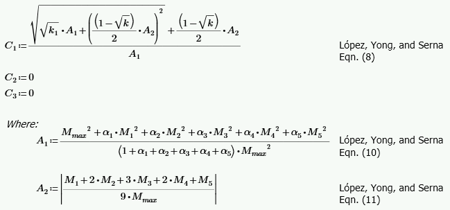
Otherwise the user can override this calculation by manually entering a value.
Note:
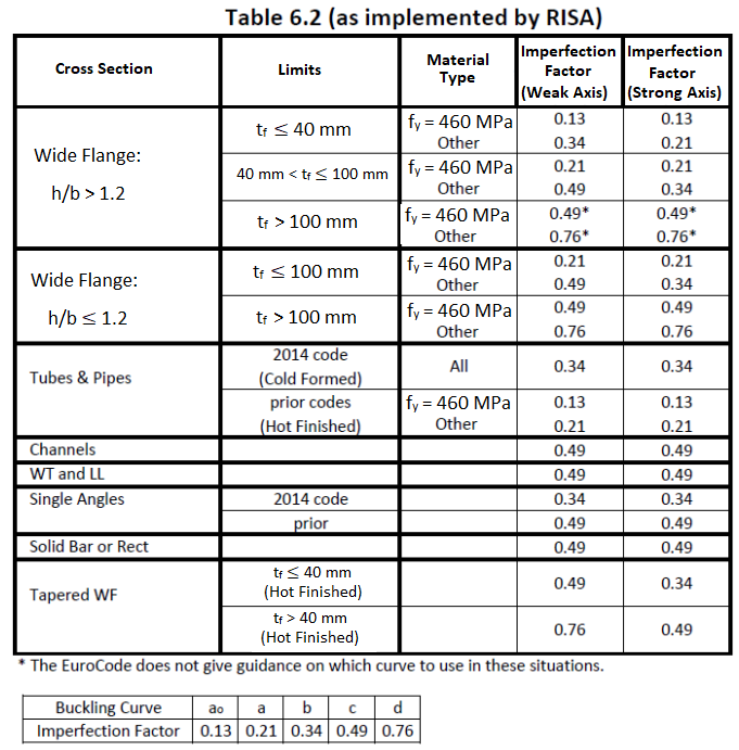
This factor is discussed in Section 6.3.1.2 of the 2014 EuroCode and is used in the calculation of the axial compression. Table 6.1 is used except for when Lateral Torsional Buckling is considered then Table 6.4 is used instead. The following illustrates what RISA uses for the buckling curve from Table 6.2:
Tapered Members - Tapered member design per the Eurocode is not supported at this time.
Lateral Torsional Buckling - The value Mcr used in the lateral-torsional buckling capacity of beams relies on a factor C1. When the C1 field is left blank it is automatically calculated per the explicit equation presented in the widely accepted article "Lateral-Torsional Buckling of Steel Beams: A General Expression for the Moment Gradient Factor" by Lopéz, Yong, and Serna (2006),, as there is no suitable generic formula presented in the EuroCode. C2 and C3 are taken as zero because RISA relies on the "general case" lateral torsional buckling equations (see section 6.3.2.2) rather that the more specialized section for rolled and welded I shaped sections (6.3.2.3).
Single Angles - Single angles are checked for axial and shear forces only for EuroCodes. No bending is considered for Eurocodes.
In beams with high shear the code implements a moment strength reduction factor (ρ), but does not place an upper limit on it. If this value exceeds 1.0 the beam has a negative moment capacity, which is irrational. The program therefore prevents a code check for these circumstances.
Parameters controlling the steel design are entered on the Member Design Parameters spreadsheet. These parameters are entered on a per member basis, and control the code checking on a per member basis.
If these entries are left blank, RISA will calculate them. The m value is influenced by the sway condition of the member and is dependent on the member's end moments, which will change from one Load Comb to the next. It's a good idea to leave these entries blank and let RISA calculate them.
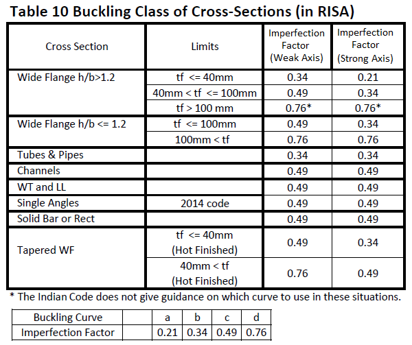
This factor is discussed in Section 7.1.2.2 of the 2007 Indian Design code and is used in the calculation of the axial compression. The following illustrates what RISA uses for the buckling curve from Table 7:
Tapered Members - Tapered WF shapes are done per the AISC ASD 9th (for the 1998 code) and LRFD 2nd (for the 2007 code) specifications at this time. The appropriate sections of the IS:800 specification will be used in a later release.
Shear Stress - For all shapes, the average shear stress is not checked per section 6.4.2 at this time.
Class 4 (Slender) Sections - No code checking is performed for class 4 sections for the IS 800: 2007 code.
Single Angles - Single angles are checked for axial and shear forces only. No bending is considered at this time.
Parameters controlling the steel design are entered on the Member Design Parameters spreadsheet. These parameters are entered on a per member basis, and control the code checking on a per member basis.
1. If this entry is left blank, RISA will calculate it based on the full length of the member.
2. When unbraced lengths (Lb_comp_top and Lb_comp_bot) are explicitly defined (enter a number), the program does not have the segmental information of the member for alpha_m calculation.
It will assume the alpha_ m used for this particular member to be 1.0.
3. When unbraced lengths (Lb_comp_top and Lb_comp_bot) are defined by physical nodes along the member with the entry ‘Segment’ typed in, alpha_m will be calculated automatically using equation 5.6.1.1(2) based on segments defined by nodes along the member.
The alpha_m value is influenced by the sway condition of the member and is dependent on the member's end moments, which will change from one Load Combination to the next.
Tapered Members - Tapered WF shapes are done per the AISC LRFD 3rd specification at this time. The appropriate sections of the ENV 1993-1-1 specification will be used in a later release.
Torsional Unbraced Length - At present the program assumes 'Lcomp' as 'Le' in case of lateral torsional buckling. Section 5.6.3 provides a procedure for calculating 'Le' which is not being addressed at this time.
Special Provisions for Cantilevers - At present the program does not address section 5.6.2 for cantilever elements.
Welded Sections - There is a basic assumption in the program that the steel sections are hot rolled not welded. Therefore, any code provisions that assume additional stresses due to welding a built-up cross section are not specifically accounted for. For the AISC-LRFD codes this generally means that the flange residual stress (Fr) is always taken as 10ksi, as for a rolled shape. The only exception is for Tapered WF shapes where it is always taken as 16.5 ksi, as for a welded shape.
Load Location - For all shape types, it is assumed that the transverse load on the member is occurring through the member's shear center. This means secondary torsional moments that may occur if the load is not applied through the shear center are not considered.
Single Angles - In all codes other than AISC 360-05 and 360-10, single angles are only checked for axial loading. Flexural effects are not considered in the code check calculation. Under AISC 360-05 and 360-10 single angles are checked for combined bending and axial about either their principal or geometric axes depending on how their unbraced length has been defined.
Net Section for Tension Capacity - The tension capacity is calculated using the Gross area. A later release will include a "net area factor" that the user can enter to indicate what the effective area should be for the tension capacity calculation.
Solid Rectangles - Solid rectangular members will not be checked for lateral torsional buckling. This limitation is only important for tall, slender shapes as LTB should not be a realistic limit state for short and thick or square shapes.
Unsupported Member Type in RISAFloor - at this time the pipes will not be designed in RISAFloor. We do hope to add their design to a future version of the program.